
Freelance Mechanical Design Engineer
At Deeplocal I worked alongside a team of talented engineers, designers, and creatives to create novel and meaningful experiences for a Fortune 100 Company. I was responsible for the rapid prototyping of the electromechanical system of a robot, fabrication of the robot and its subsystems, and improving the designs of the subsystems for manufacturing. I added to my experience in design, PCB prototyping, 3D printing, laser cutting, machining, woodworking, and programming.

CleanRobotics - TrashBot
TrashBot is a robotic trash bin that uses AI to sort landfill waste and recyclables. I iterated and improved the design of the TrashBot from a first prototype to small batch manufacturing prototype. I controlled the CAD designs and documentation in Autodesk Fusion 360, created a BOM, and sourced all of the components from foreign and domestic suppliers and manufacturers. I controlled quality control with the manufacturers during orders and wrote documentation for inspections. Through the early iterations, I machined and fabricated components and assembled TrashBots during which I an extensive assembly guide. Additionally, I prototyped new innovations, and supported funding, marketing, sales, and business strategy.
Over 18 months, I assembled and or oversaw the assembly, testing, and distribution of 15 TrashBots, nearly all of which are still deployed and functioning. Toward the end of my employment, I established a production plant located in Point Breeze in which technicians still carry out light manufacturing, assembly, testing, and distribution.

Functionality
Item disposal is detected by an array of IR transmitters. After detection, the lid is closed by a stepper motor driven pin-slot mechanism. The item is weighed by a ‘tray’ beneath the actuating chamber while the item is illuminated and photographed The item is identified as either landfill waste or recycling and disposed of by a stepper motor and worm gearbox driven actuating chamber. Time-of-flight sensors located in the top measure the fullness of the bins. Data from the unit is relayed to a dashboard in real-time, which can be accessed by customers visually analyze data collected by the TrashBots.
The electronics in the top plug into a breakout board making the top modular, easier to maintain, and quicker to assemble. The breakout board is connected by a ribbon cable to a primary PCB located on the chassis of the TrashBot.
The videos below show the functionality and user flow of the product.

Design
The top of the TrashBot is milled out of a solid block of ABS plastic, however, it is designed for vacuum forming when a larger production scale is reached. The tops come pre drilled for the easy assembly and can be assembled by one person in just over an hour.
The frame of the TrashBot is composed of four sections and a base plate that can be flat-packed in a box only six inches deep. The frame is assembled with rivets and can be assembled by one person in under 30 minutes.
Assembly of the shell is comprised of riveting two panels the sides, and two doors all composed of bent sheet metal. With assembly of the actuating chambers and other finishing touches, the complete assembly and testing can be done in one day by one person.
As industrial machine intended for mass production and consumer use, cost was the primary design driver. The TrashBot can be manufactured and assembled in under two weeks for around $3,500 with labor.
(Above) User flow and disposal
(Left) CAD animation of disposal process

Fenner Precision - Project Orion
At the University of Delaware, I was on a senior design team of four mechanical engineers working for Fenner Precision, a global manufacturing leader in elastomeric solutions. We designed an automated adhesive delivery system for digital printing rollers that minimized operator time and manual input, improved adhesive coating quality, and increased the speed of the process. In 12 weeks we successfully delivered a functioning prototype to enter testing.
We followed a strict design process researching and benchmarking other solutions, gathering customer wants and needs, creating design metrics, and concepting and developing the design. In 12 weeks, we sourced all of the components from suppliers and machine shops, assembled wired, programmed and tested the machine, and delivered a functioning prototype for further testing and development.

Functionality
Large rollers were placed on a rack that retracted into the machine and then raised by pneumatic linear actuators. A motor assembly engaged with the rollers then rotated them while the gantry traversed each roller, coating them in a thin adhesive film. The motion was controlled by a number of limit switches and solenoids connected to an I/O controller which we programmed with ladder logic.
The design was especially successful in achieving the specific adhesive coating thickness tolerances, and drastically decreased the number of necessary worker inputs of the coating process.
Adhesive Delivery System
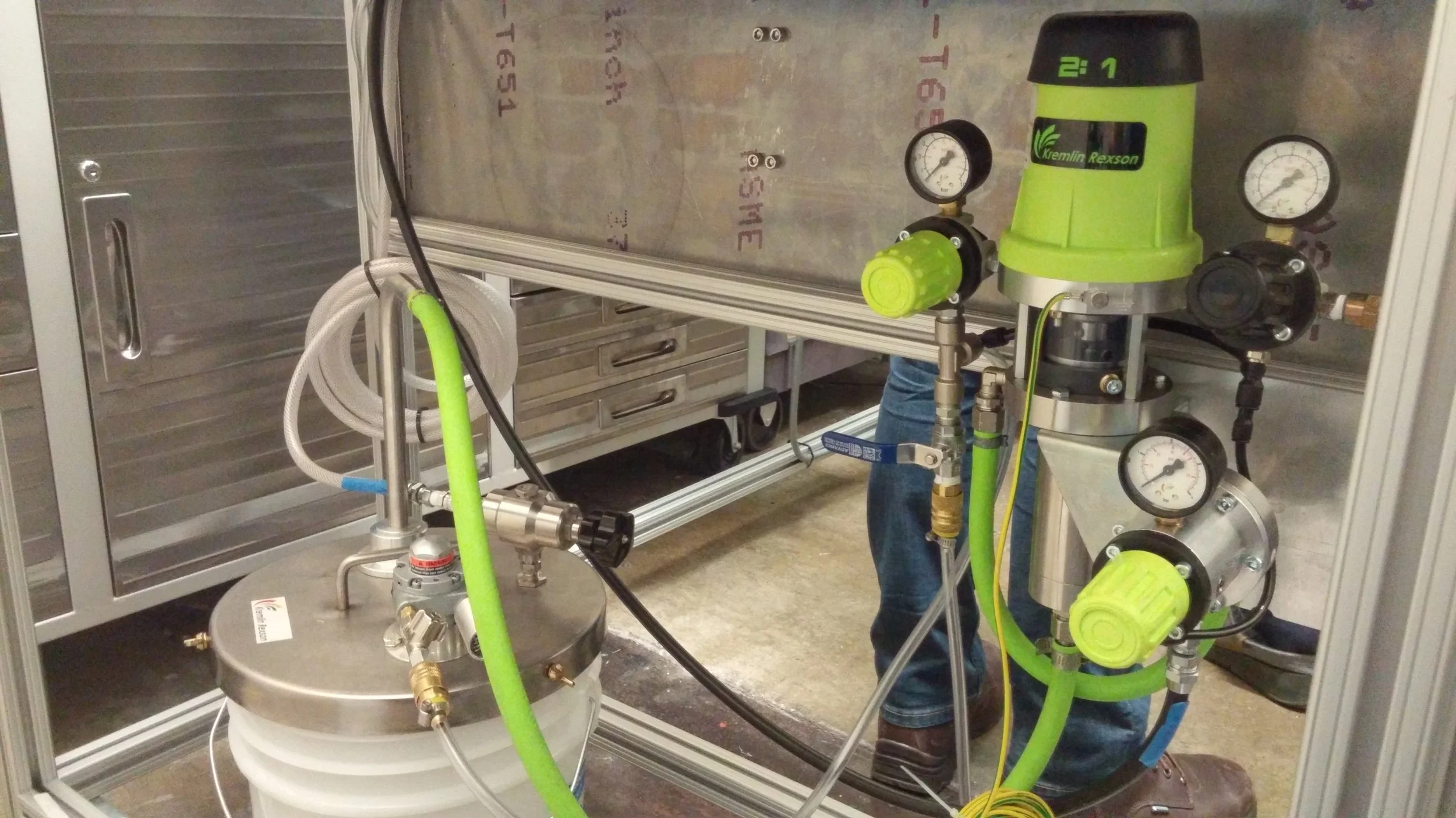
I was responsible for designing and sourcing components of the adhesive delivery system and the electromechanical system. The adhesive delivery system consisted of an adhesive reservoir with a pneumatic driven agitator, a pump, regulator, and an applicator.
The adhesive delivery system components were sourced from OEMs and the mechanical components from suppliers and local machine shops. We assembled the components and tested the machine onsite in their Lancaster, PA location.
I gained my first experiences with designing and sourcing complex mechanical components communicating with OEMs and machine shops, designing pressure regulated pneumatic systems, and assembling and testing an industrial automated machine.

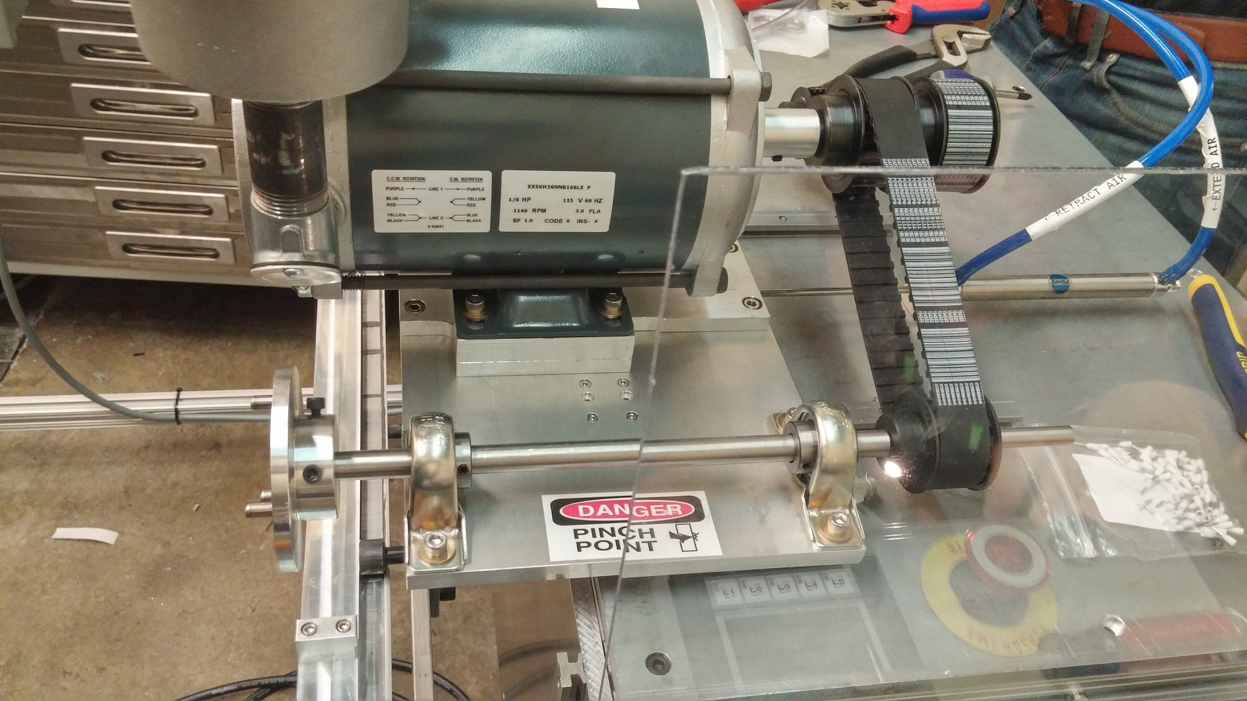
(Above) Driven by a belt drive, three pronged keys on the shafts to engage with rollers. The drive sits on linear rails with a linear actuator to engage with the rollers
(Left) Adhesive spray gun attached to adhesive delivery and pneumatic actuator lines
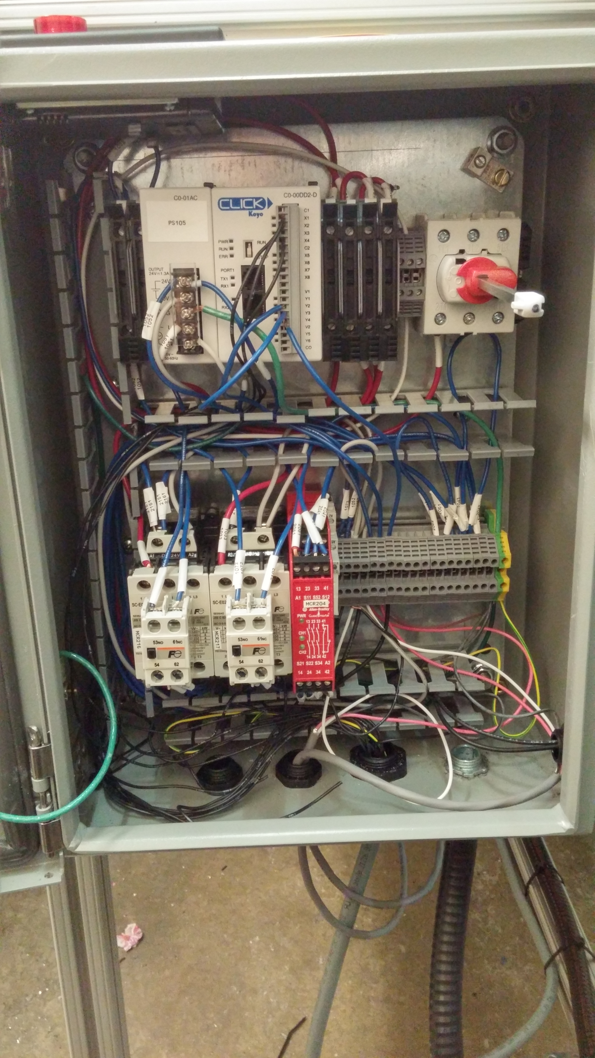
Control box , I/O controller programmed with ladder logic

Pneumatic fluid and air lines attached to the applicator


Xinqiao Jia Research Team - Vibrational Bioreactors
I designed and machined two vibrational bioreactors for a biomedical research team at the Unviersity of Delaware. The bioreactors used speakers to vibrate silicon membranes with the elasticity of human vocal tissue. The research team cultured stem sells on top of the silicon membranes and vibrated the membranes at the frequency of human speech. The stem cells were tested for signs of growth into vocal tissue cells. Additionally, I wired and calibrated the bioreactors to vibrate uniformly using a laser measurement system and function generator connected to the amplifier.
A third bioreactor was created by an outsourced machine shop which uses DC motors and cams to strain the membranes more than the vibration which mimics speech therapy. I created silicon membranes with special speckle patterns which allow a a VIC3D bifocal camera system to follow the individual dots during the straining process The accompanying software then created a 3D strain map of the membrane for analysis by the research team.
During this position, I gained nearly 200 hours of machining experience, learned the nuances of machining a material that is prone to cracking and melting, and learned special techniques to fixture thin sheets during machining. I also learned how to write technical papers and study and manage data for review.

Design & Functionality
The bioreactors consist of eight speakers housed pockets machined into two large aluminum blocks (one on each side of the bioreactor). An acrylic block is mounted to the face of each speaker, with a top block bolted to to the bottom block. A silicon membrane is sandwiched between the blocks. The stem cells are suspended in a saline solution on the membranes and vibrated by the speakers.
The speaker assembly is enclosed by a moisture tight chemical resistant polycarbonate housing. The housing has doors mounted on piano hinges that close around the blocks with a tight seal. In the center of the housing is an amplifier which controls the frequency and pitch of the speakers. This is assembled with an acrylic cement that melts the polycarbonate pieces together along the joint creating the moisture tight seals.
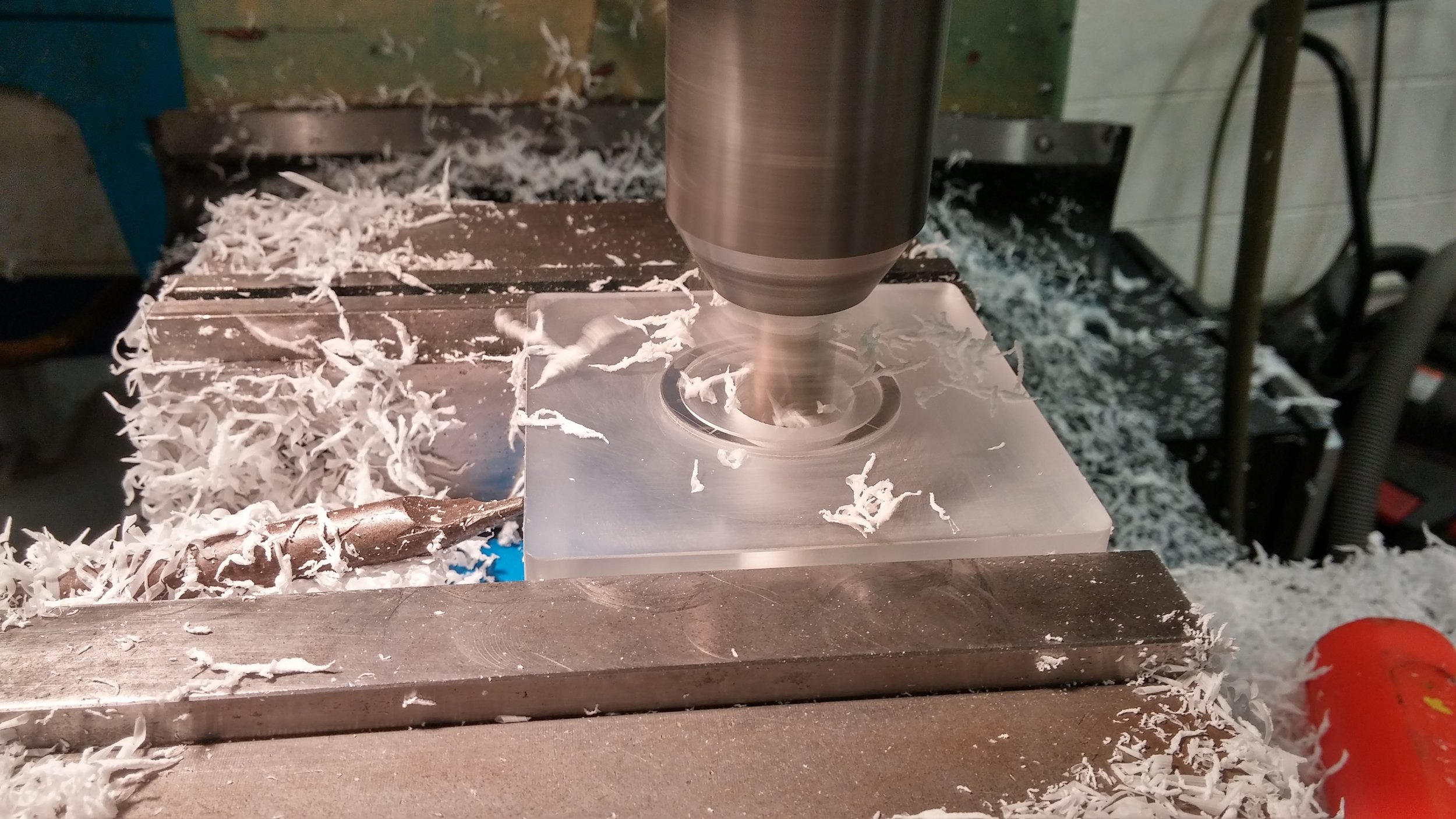
Cutting the inner pocket in one of the bottom blocks using a CNC mill

Drilling the mounting holes in one of the top blocks